An Approach to UAV-Based ELINT – JED, December 2017
– By P. Michael Gale –
The resurgence of more conventional threat scenarios on top of the ongoing asymmetric conflicts around the globe, combined with the downing of the Malaysian Air flight by a BUK system has started to capture the public’s attention to what was once one of the staples of our community, the radar-guided surface-to-air missile (SAM) threat. The ongoing evolution of the SAM threat and its capability to establish Anti-Access, Area Denial (A2AD) bubbles in potentially contested locations around the world has certainly brought into focus the long-neglected Suppression of Enemy Air Defense (SEAD) mission and the means by which this can be achieved.
In preparing to plan on the suppression of the systems that make up an integrated air defense (IAD) network within the A2AD bubble, we are quickly drawn to the conclusion that we will need to mount a comprehensive ISR mission that can establish and maintain the electronic order of battle (EOB) and disposition of the high-value sensors and associated weapons systems.
The primary ISR mission will involve effective deployment of signals intelligence (SIGINT) assets that can collect both electronic intelligence (ELINT) and communications (COMINT) on the elements of IAD network. Historically ELINT, especially of a strategic nature, was the domain of manned platforms and this remains the dominant solution today. However, we have seen a growing trend towards migrating the SIGINT mission to Unmanned Aerial Systems (UASs).
ELINT SYSTEM ARCHITECTURE APPROACH
The architecture and specification of a UAS and its airborne platform, often referred to as an unmanned aerial vehicle (UAV), to be used for ELINT needs to be arrived at through a careful process of engaging with the users, operators and all the stakeholders, combined with input and guidance from subject matter experts (SMEs) and engineers with many years of real-world hands-on operational ELINT system design experience.
The approach to the UAS ELINT architecture involves defining the needs and imperatives, defining the Concept of Operations (CONOPS), considering the threat and the range of mission profiles and scenarios.
USERS
Before discussing the CONOPS, a word about the candidate users can provide some context to the various approaches that a SIGINT or an ELINT system architect might adopt, since it is often the case that the users are international (non-domestic) with different constraints, different perceptions of the threat and unique use scenarios. It can be the case that they are constrained by budgets, with limited national intelligence infrastructure. Likely, the user will approach the acquisition of the UAV with a desire to maximize mission mix for their UAV assets.
CONOPS
In constructing the CONOPS from which will come the solution, it is important to lead the user through the thought process. The first consideration in the CONOPS is the deployment of the ELINT assets. Will it be used for tactical and strategic collection, or both? Strategic ELINT is usually driven by national interest, which may include establishment of the strategic EOB, an early warning or “tripwire” mission with the ability to detect changes in posture, as well as the more traditional tasking of emitter parameter data collection to support a national emitter data base (NEDB) and/or emitter parameter library programming, in addition to scientific and technical collection. Tactical ELINT is more about immediate threat location in support of SEAD, as well as the detection of incursions or the presence of a particular threat.
In the context of the strategic and tactical ELINT missions, the A2AD bubble requires the user to think about whether to operate the platform in the stand-in or stand-off role. Operating as a stand-off ELINT collector means the UAV operates outside of the territorial boarder or territorial waters. More importantly it operates beyond the lethality envelope or “enticement to launch range” of the long-range SAM threats.
Stand-in operations offer a much clearer picture in that we can say the ELINT UAV collector will be within the lethality envelope of the IAD network making up A2AD environment and often within the territorial boarder of the potential or actual adversary and definitely within the radar coverage of the bubble.
Having defined the nature of these missions, we can now establish a set of user needs and expectations for the UAV payload and associated mission systems.
THE THREAT ENVIRONMENT
Whether it is decided to operate within the A2AD environment as a stand-off or stand-in collector, it is critical that consideration be given to the potential adversarial threat environment. From an ELINT perspective, it is necessary to understand what is important both for the mission and the survival of the UAV platform. This is especially true because the IAD sensor networks within the A2AD bubble have improved, and this now makes any radar a potentially lethal emitter. Combined with this situation is the trend toward low-probability of intercept (LPI) radars in the IAD networks. Characteristics which were once the exception are now common place, including:
Common Radar Characteristics • Pulse Compression • FM Bi-Phase/Poly-Phase • Frequency Agility • Interpulse and Intrapulse • Beam and Power Agility • Pulse-up • Ultra Wideband • Very Short Pulses
Adding to this complexity, is the fact that the emitter population is much less well defined, due to international radar technology proliferation, as well as older legacy systems being upgraded by the insertion of solid-state transmitters and more advanced digital signal processors.
THE PLATFORM
Platform Considerations
For a UAV prosecuting collection against an IAD network within the A2AD scenario, platform selection is one of the leading imperatives and ultimately becomes the primary operational constraint. There exist many types of UAV platforms, and the platform selection represents a trade-off for the user, since ultimately the platform limits the ELINT payload’s size, weight and power (SWAP), which in turn constrain the EW system and SIGINT system capability. In addition to these constraints, the user often wants to employ the UAV for different missions, which drives requirements for operational flexibility.
For many users, mission flexibility is the key. Whether equipped with a range of payloads or a fixed mission-specific payload, each UAV type offers varying pros and cons, including operational endurance, operating altitude, platform size and SWAP. Here, the user is faced with a number of competing trade-offs, some of which can be resolved by developing a carefully thought through CONOPS.
Platform Types and Selection
A number of organizations have attempted to clarify the characteristics between UAV types by establishing categories. These are essentially broken down by key performance characteristics relating to operational altitude, endurance, range and all-up weight capacity. In general terms, we can consider the choices for UAV types for ELINT falling into Mini, Tactical, Medium Altitude Long Endurance (MALE) and High Altitude Long Endurance (HALE).
In selecting the UAV platform for ELINT, the stand-in and stand-off scenarios will demand UAVs with different endurance and EW capabilities, which in turn reflect back on the ability of the platform to lift the payload for the desired mission endurance. More importantly, the need to consider other factors comes into play.
These factors are influenced by the definition of the mission scenarios and the threat. Specifically, if the UAV is intended to fly outside of the lethal envelope of the IAD network within the A2AD bubble, the aircraft must still fly at sufficient altitude that it’s ELINT system can intercept emitters deep inside the A2AD bubble (again, while flying outside of the lethality zone). A second factor in the selection of the UAV relates to the payload and in particular the size of the antenna array to be used for the ELINT system and for that matter the COMINT system in a SIGINT designated platform.
For high direction-finding (DF) accuracy, sensitivity, rapid response, as well as maximum flexibility, the dominant consideration must be the ability of the UAV to support long DF baselines and large aperture antennas. Beyond these factors, we also have to consider the nature and the dissemination process of the ELINT data. These considerations will bring demands regarding onboard processing in support of data compression and demands on the data link between the UAV and the ground control station.
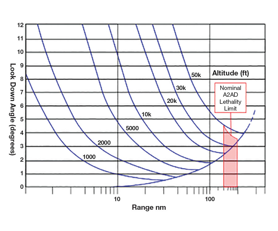
Fig. 1: Height vs. range. vs. lethality.
If the goal is to fly strategic ELINT against threats inside of the A2AD bubble, then from Figure 1 we can see that the UAV must support an operational ceiling above 30kft to ensure operation outside the A2AD lethality zone and a reasonable radio horizon for the ELINT system. This need clearly drives the selection towards a MALE or HALE type platform selection.
OTHER CONSIDERATIONS
At this point, it is worth providing some words on radar cross section (RCS). By the nature of their size and sometimes by design, UAV platforms offer an improved RCS, which is of great advantage for the ELINT mission, especially if it is intended to fly a stand-in mission. However, many UAVs today, especially MALE and HALE types, have such a lift capability that users often decided to add a number of other sensors, such as synthetic aperture radars (SARs), electro-optic and infrared (EO/IR) sensors, and even jammers, in support of multi-purpose capability. These items will inevitably add to the RCS of the platform and make survival in the stand-in mission much less certain.
Another factor in the mission selection and nature of the ELINT platform is the fact that as the UAV on an ELINT collection mission penetrates further into the A2AD bubble, it starts to lose the economic competition against the threat. At the edge of the bubble, the cost of a kill for the threat system typically is high. The further the UAV flies into the bubble, however, the more it encounters shorter-range SAM systems where the cost of a round is less, the threats are more numerous and the likelihood increases of being engaged by a salvo.
In addition, the UAV’s data link becomes an important element of the mission system that is highly influenced by the CONOPS and mission scenario. For example, a strategic collection mission that is part of a routine program of maintaining the NEDB, in which the platform is operating in a stand-off role, can store data onboard the UAV until the system has returned to base. In this scenario, the UAV’s datalink system does not have to be demanding in terms of SWAP. On the other hand, a tactical collection mission conducted at the beginning of a conflict in contested airspace creates a different set of operational demands. In this situation, there is a need to feed operational commanders real-time ELINT and EOB data regarding an ever-changing threat that will be mobile (shoot and scoot). This would require varying degrees of data link capacity depending on whether the data link is streaming and or supporting queries and resolving ambiguities on locating and identifying specific emitters and associated weapon systems.
ELINT SYSTEM CONSIDERATIONS
Once the CONOPS and operational ELINT missions have been identified and the platform has been selected, the user must now consider the ELINT system itself.
Threat Band Coverage
First, the ELINT system must be designed to cover all of the emitters of interest in the A2AD bubble. In this case, it can be argued that the frequency band coverage should be from A Band to J Band, which parametrically would approximately be from below 100 MHz to above 18 GHz. Of course, such a broad frequency range will add to the antenna array requirements and complexity on the platform, among other things, and is one of the driving requirements
POI vs. Detection
Another consideration is probability of intercept (POI). Depending on your point of view, POI is really more than just time coincidence of two events. Before detection can occur, interception must have occurred. The probability that a given signal is detected and processed by the system is defined as the POI. This is a function of the scenario, the signal and the receiver system. Many types of staring receivers have a high POI, but they often have much less sensitivity. Detection is a function of signal level, noise level, detection thresholding and processing.
IFOV
Historically, due to the predominant use of scanning technology for ELINT (spinning reflector antenna and scanning superheterodyne receiver), POI has been about the coincidence of dwells, such as beam on beam, which can be thought of as instantaneous field of view (IFOV) vs. IFOV, beam on frequency or frequency on frequency. To improve POI, an ELINT system must increase its spectral, temporal and spatial instantaneous domain coverage (fields of view), and ultimately POI represents a trade-off between coverage versus cost.
In order for the UAV flying an ELINT mission in a loiter pattern to support continuous collection, the ELINT system needs a staring capability. In other words, the system needs a wide spatial (angular) IFOV. On the other hand, in an ELINT mission attempting to support the establishment of an ever-changing EOB, the need for DF precision is also important to the discovery and assessment of the high-priority elements of the IAD network. In addition, one way of looking at bandwidth is that it represents the ELINT system’s spectral IFOV and to improve POI, the wider the bandwidth the better. Of course, the opening up of the ELINT system’s IFOV in more than one domain increases it vulnerabilities to interference, and this issue must form part of the system design considerations.
High Interference and EM Spectrum Encroachment
The ongoing trend of reallocating portions of the Electromagnetic Spectrum (EMS) for commercial use has added a growing number of interfering signals into the channels adjacent to many emitters of interest. These interfering signals are often in-band for wideband operating modes. Below 6 GHz, spectrum congestion makes it difficult for a wide-open receiver to detect many of the key radars in the A2AD bubble. Moreover, the drive to high POI performance, by its very nature, opens up the ELINT system to occurrences of interference.
The Electromagnetic Environment (EME) in both peace and war will contain a high population of intentional (jammers) and unintentional interferers. When operating against the A2AD bubble, especially in large population areas or around a littoral environment close to major ports and shipping lanes, the ELINT system will be exposed to myriad interfering signals. These can severely degrade its operation and also result in the collection of a significant amount of poor-quality data. Poor-quality data exacts a price from the EW cycle, since it consumes precious analysis time that is critical during the opening phase of a conflict. Furthermore, time coincidence between the threat emitter signal of interest and any interfering signal also creates the potential for parametric errors that result in ambiguous identification and emitter sorting congestion.
To support high immunity to interference, the ELINT system must use multiple layers of hardware filtering and a high-dynamic-range digital receiver. Hardware filters are important throughout the system architecture, since digital filters and channelizers are of virtually no benefit, as the analog-to-digital converter in the digital receiver approaches saturation. This also implies that the digital receiver needs to have a digitizer that can support a high instantaneous dynamic range, which should be as good or better than its older analog equivalent, where 60 to 70 dB spurious free dynamic range (SFDR) was not uncommon.
Filtering to improve immunity to interference in the ELINT system’s low noise amplifiers, necessary for ensuring good system sensitivity through a low system noise figure (NF), is also an important consideration. In a dense and interfering environment, the front-end amplifiers could be driven hard enough that the intermodulation products generated as they approach compression, unnecessarily increase the ELINT system’s false alarm rate (FAR). As the emitter density in environment increases, the more exacerbating the problem becomes.
Interestingly, very few, if any, ELINT system specifications contain a system level measure of interference immunity or signal to interference ratio (S/I). In part, this is due to having no internationally agreed method by which such a test could be conducted between alternative ELINT systems architectures. A contributing complexity would be agreeing on the time coincident mix of signal types and characteristics and expected outcomes.
Sensitivity
Good ELINT receiver sensitivity is critical to enabling the UAV to operate outside the A2AD bubble. Intercept for the ELINT system will directly rely on sensitivity to achieve detection of emitters inside the bubble at long range.
The operating sensitivity of an ELINT system in its simplest form is based on the well known and so called “black box” equation where:
System Sensitivity = KTBNF(S/N)req G Where: K = Boltzmans Constant = 1.38 x 10⁻²³ Joules/K T = Temperature at receiver input = 290 °K B = Receiver bandwidth in Hz NF = Receiver Noise Figure (S/N)req = Minimum signal-to-noise ratio (SNR) required to achieve the receiver’s operational performance G = Antenna and/or System gain
In evaluating the sensitivity equation, we can see that the expected sensitivity is influenced by receiver bandwidth (sometimes referred to as the instantaneous bandwidth IBW) and antenna directional gain/system gain. The good news is that these performance measures are within the control of the user in terms of ELINT system design and operation.
Signal-to-Noise Ratio
The goal of any ELINT mission is the collection and recording of high-quality data, which means recording with the highest signal-to-noise ratio (SNR) possible. However, the minimum SNR needs to be considered to achieve a given minimum performance, such as reliable emitter detection with an acceptable false alarm rate and sufficiently accurate DF and parametric measurement for identification purposes.
This minimum achieved SNR will depend on the user and will vary between systems and technology and whether there is a human or machine or both involved and their respective capabilities and skills.
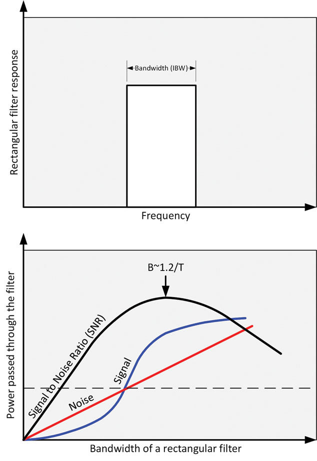
Fig. 2: SNR required.
Figure 2 (above) shows the typical minimum SNR required for various ELINT system capabilities and needs.
Measurement Accuracy
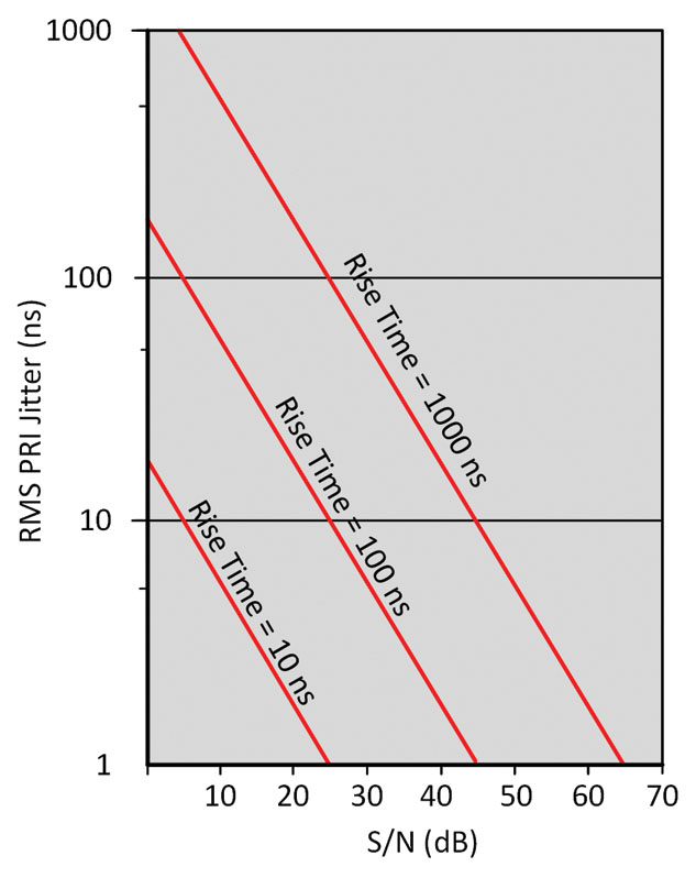
For effective ELINT system measurement accuracy and to collect and record high quality ELINT data, the ELINT system must be designed to maximize the SNR at any given time under a given scenario. As a goal, we need to reduce noise and increase signal. Noise limits measurement accuracy, dynamic range and data quality. For example, in the measurement of pulse repetition interval (PRI), a key emitter parameter, we will see time interval Jitter as a function of SNR. Figure 3 gives an indication of the effect of SNR to PRI measurement accuracy.
Fig. 3: PRI jitter vs. S/N for various rise times.
Matched Receiver
As we have seen, measurement accuracy is dominated by SNR. In order to maximize signal to noise, it is important to operate the ELINT as close to a “matched receiver” as possible. Also, referred to as matched filter, this is the appropriately shaped linear filter for maximizing the SNR and is a common design approach in radar. In older conventional radar systems, “matched receiver” is when the intermediate frequency (IF) bandwidth approaches the reciprocal of the pulse width. In practical implementations, SNR tended to 1 dB worse than the true matched filter.
For the ELINT receiver, where high SNR is very desirable, matching the receiver to the signal is an important consideration. Modern radars, however, use pulse compression techniques, so the user must not only consider pulse width, but rather the receiver needs to match to the Time-Bandwidth Product. For example, the user should consider carrier frequency deviation range for radars with Chirp, if they want to look at high quality collection/recording of intrapulse. Note also that for DF and other considerations the filters selected should have flat pass band group delay characteristics.
Environmental
The ELINT system that will be installed on a UAV will be subjected to very much that same set of conditions as those of a manned platform and will not be discussed in detail here. Suffice to say that the antenna array installation and environment performance are likely to be the most challenging.
ADDRESSING THE CONSIDERATIONS
From the foregoing discussion on the considerations the ELINT system must address, we can then discuss how the user in the design of the ELINT system might address these considerations.
Threat Coverage
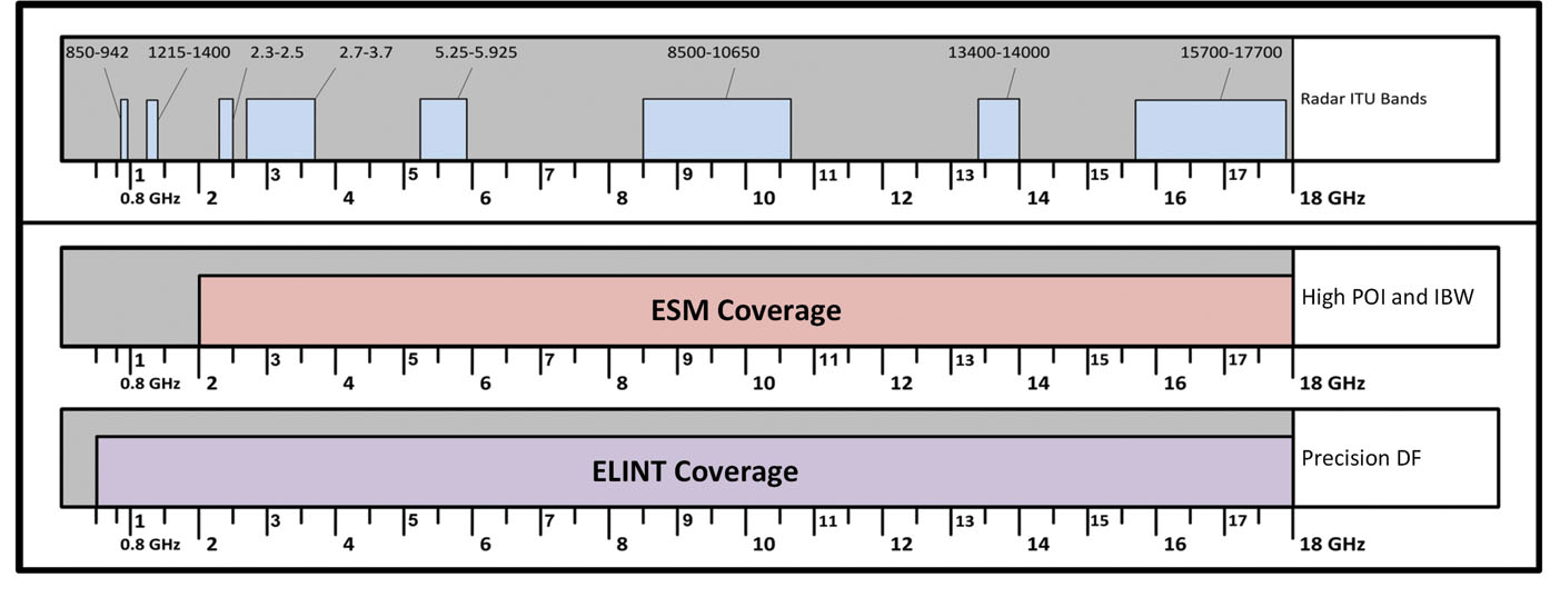
The actual frequency coverage of the system will be driven by the threat, the CONOPS and the mission imperatives, as well as by the adopted doctrine. The highest value emitters in the A2AD bubble will mainly be covered by a 0.5 to 18.0 GHz system for a stand-off mission, as shown in Figure 4.
Fig. 4: Nominal ELINT frequency coverage.
The concern about the extremes of frequency coverage, which are the VHF and millimeter wave (mmwave) emitter band respectively can be thought of as exceptions. In looking at the A2AD bubble in terms of the high-value emitters, it can be argued that the VHF band is more important than the mmwave, yet VHF is often not covered by traditional ELINT systems. For the mmwave band, the problem is that these signals are subjected to the propagation losses due to atmospheric and weather conditions. These conditions are such that under a range of aspect angles and rain rates for example, the propagation losses can amount to 10s of dBs variation, and this is why mmwave is associated with relatively short-range operation and weapons systems or the terminal phase of a long-range missile.
In addressing coverage at the extremes, any ELINT system architecture can be evolved to take these into account. The issue is that there is a cost to adding both of these extremes. In a trade-off where you can only afford one, which would be the better option? In this regard, one might think about the exploitation of a COMINT system that may be onboard the platform. In this case, it may be that the hardware can be replicated or adopted at some level in the architecture to satisfy the ELINT feed without compromising the operational needs of the COMINT mission.
High POI and Immunity – Hybrid Receiver Architecture
To address the divergent needs of high POI and immunity, the user can decide on a hybrid receiver architecture using the strengths of one receiver to complement the weaknesses of the other and vice versa. A combination of receiver technologies, such that one receiver is acting as a traditional ESM system, where precision, accuracy and immunity are traded for POI approaching 100% spatially, spectrally and temporally. This type of receiver might consist of an amplitude comparison monopulse DF or omni antenna combined with an instantaneous frequency measurement receiver.
The other major element of the hybrid receiver architecture would address the considerations of high accuracy DF through the use of a linear interferometer array and improved immunity to interference with a multi-channel superheterodyne digital receiver.
High Immunity to Interference
To support high immunity to interference, the ELINT system must use multiple layers of hardware filtering and a high-dynamic-range digital receiver. Hardware filtering is important throughout the system architecture, since digital filters and channelizers are of virtually no benefit if the analog-to-digital converter approaches saturation. This also implies that the digital receiver needs to have a digitizer that can support a high dynamic range with a high effective number of bits (ENOB), which should be as good or better than its older analog equivalent, where 60 to 70 dB SFDR was not uncommon.
Filtering to improve immunity to interference in the low noise amplifiers, necessary for ensuring good system sensitivity through a low system NF, is also an important consideration. In a dense and interfering environment, the front-end amplifiers could be driven hard enough that the intermodulation products generated as they approach compression, unnecessarily increase the ELINT system false-alarm rate (FAR). As the emitter density in the environment increases, the more exacerbating the interference problem.
Signal Bandwidth
The pursuit of establishing an EOB against high-value emitters requires that we maximize SNR and have modes in the ELINT system that support operation as close to “Matched Receiver” conditions as possible. One very useful tool to achieve matched receiver conditions in the ELINT system is the use of selectable hardware and digital filtering to enable the operator to select a system IBW that approaches matched conditions and high S/N.
Intrapulse
For an ELINT system to collect intrapulse, the user must consider the full range of intrapulse data of interest and this must then address the bandwidth and other receiver parameters to ensure quality ELINT data.
ANTENNA OPTIONS
Although the discussion, so far, has revolved around the need for large IFOV and high accuracy DF, the MALE/HALE platform not only makes it feasible to consider mounting a relatively long baseline interferometer to accommodate high-accuracy DF at the lowest frequency, it also supports other antenna options. For example, it is quite appropriate to consider the use a spinning dish antenna that offers significant directional gain in combination with the interferometer.
High-Accuracy DF
High-accuracy DF is achieved by precision angle-of-arrival (AOA) measurement over a wide instantaneous bandwidth and wide instantaneous field of view. This is critical to rapidly establishing changes in the EOB and to support SEAD operations. To achieve this, fast and accurate DF, as well as rapid location estimates and precision AOA measurement must be made on a pulse-to-pulse basis to support real-time de-interleaving using AOA as part of the emitter-sorting algorithms. These demands drive the system solution towards the use of single- and/or dual-axis linear phase interferometer DF designs.
Directional Gain
Specifically recalling the sensitivity equation from earlier in this discussion, we can see that having gain –and specifically directional gain – from an antenna can make a significant contribution to sensitivity and ultimately SNR during collection. It also enables higher SNR under non-ideal conditions, where matched receiver conditions are not possible due to emitter agility or occulting modes that remove the opportunity to use appropriate signal processing techniques for the real-time operation.
With a MALE/HALE platform, the installation of a spinning dish antenna is not only a beneficial option, but it is often feasible because many of these platforms are often modified to mount SAR, and substitution of the SAR antenna by a spinning high-directional-gain antenna may not represent a significant change to the platform.
One by-product of the spinning dish antenna and its high directional gain is its benefit to the potential of extending ELINT operation to the mmwave band for longer-range intercept.
INSTALLATION AND INSTALLED PERFORMANCE
Once the ELINT system architecture and design has been defined to address the considerations outlined, the user must address installation and installed performance.
Installation
Installation considerations beyond the conventional items of environmental and SWAP revolve around the location of antennas and associated RF components. From a user perspective, we must consider where to mount the antennas from the point of view of the operational imperatives and the constraints imposed by the selection of the platform.
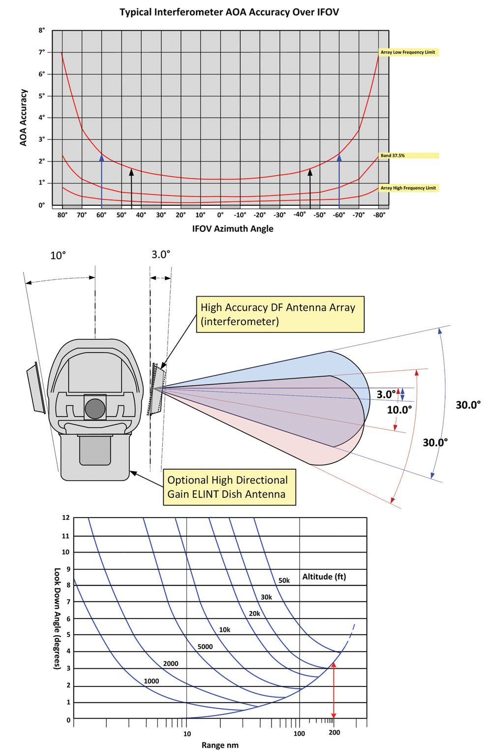
The key for the ELINT system performance is that of the antenna system that is responsible for delivering IFOV (POI) and DF accuracy. We must consider installation such that it avoids any obstructions within the specified IFOV.
Beyond this is the need to install the antenna array such that it is positioned for the mission at hand. For example, the installation for a stand-in versus a stand-off mission creates some considerations in terms of boresighting the antenna.
In Figure 5, we can see that the DF accuracy of an interferometer is best at the boresight. Recall also in the stand-off mission that the radars of interest may be deep inside the lethality zone. Then it is likely that the ELINT targets are on the order of 200 nmi from the ELINT platform, and for DF accuracy the lookdown angle should be set accordingly. On the other hand, a stand-in mission may drive the boresight to a steeper look down angle.
Installed Performance
With respect to installed performance, the ELINT system must be able to deal with any physical effects of the platform on the system performance, which often relates to interference or blockage of the operational IFOV from wings or other antennas.
Mutual Interference
Beyond the special considerations of the installed performance, the user must address the mutual interference problem and the ELINT system design must not only deal with the potential interference for the EME, but it must anticipate the fact that the onboard emitters will compromise its ability to effectively conduct its mission. It is of little benefit if the ELINT system performance is degraded by on-board emitters, especially high-duty-cycle data links, which in this case will present the ELINT system not only with interference at the operating frequency, but often at frequencies that are harmonically related or produced by intermodulation.
SIGINT/COMINT
This article has not addressed the COMINT aspect of a SIGINT-based UAV operating against the IAD network. Nonetheless, at the periphery and deep inside the bubble, multiple long-range early-warning radars (most of which will be mobile or easily transportable) will share track data over LPI data links with other radar systems, their long-range SAMS and associated weapons systems, as well as their command nodes. Therefore, in building the picture of the IAD network, the data links that network the radar systems together, as well as the SAM systems, must be an essential part of the intelligence picture, especially in anticipation of SEAD operations.
AEA
Beyond the use of a UAV to perform the ELINT mission at the edge of or inside the A2AD bubble, we can also imagine that a suitably designed UAV and payload can be used to provide airborne electronic attack (AEA), with some of the same advantages as afforded the ELINT platform. However, this discussion is outside of the scope of this article, and is a topic for the future. ♦
About the Author:Mike Gale is the Director, EW Systems, at Telemus in Ottawa, Canada. For the past 10 years he has served in a variety of roles in ELINT and AEA programs at Telemus. Mike began his career as an engineer for Plessey Radar Ltd, UK and following a move to Canada, headed up the new EW business at Canadian Astronautics Ltd. in 1981. He joined Telemus Electronic Systems, Inc., in 1984 and lead a number of ELINT related R&D programs prior to serving as President and CEO of the company for many years, before it was acquired by Ultra. Mike has served as member of the Defense Research Establishment Ottawa EW R&D peer review committee and in 2015 Mike’s contribution to EW was recognized by the AOC, when he was selected to receive the 2015 Joseph W. Kearney, EW pioneer award.
If you enjoyed this article, please share. If you would like to read more articles like this one, we encourage you tojoin the AOCto receive a copy of JED every month.