When jamming communications, great emphasis is placed on the jammer’s signal strength at a victim receiver’s location, when in fact there should be an equal emphasis placed on the space, or “link distance,” between the transmitter and receiver. The link distance between a victim receiver and transmitter (or transceivers) is crucial because either the receiver or transmitter can move close enough to the other and “burn through” the jamming. The term “burn through” refers to an effect where the transmitted signal strength, at the victim receiver, is greater than or equal to the signal strength from the jammer. For this paper, the term “parity distance” describes the maximum distance a transmitter can be located from a victim receiver and equal the signal strength from the jammer. Any distance less than the parity distance means the transmitter signal is closer and its signal is stronger than the jamming signal, thus rendering the jamming signal less effective or useless. This scenario can create a false-positive condition from an electromagnetic attack perspective; thinking the victim receiver is disrupted and reporting that effect to the tactical commander. This article outlines a technique to estimate parity distance between transceivers, using a well-established algorithm.
Electromagnetic Warfare Axioms
For this article, there are five basic electromagnetic warfare “axioms” (or postulates) which help define the scope of effectiveness for both jamming and communications activities:
- Maximum range is a function of antenna heights. The transmitting and receiving antennas must “see” each other (i.e., have “radio line-of-sight”) in the electromagnetic operating environment (EMOE) to communicate and/or effectively jam a victim receiver. Increasing the height of the antennas above ground increases the maximum range. Note: the maximum range is the greatest distance a signal can travel without consideration of diffusion.
- Maximum effective range is a function of receiver sensitivity. As a signal travels farther away from the transmitter, it becomes weaker. For a receiver to detect a signal, it must be as sensitive as the strength of the arriving signal. The weaker the signal, the more sensitive the receiver has to be. Note: the maximum effective range is the maximum distance at which a signal may be expected to be accurate and achieve the desired effect.
- Signal strength is a function of transmitter power. The greater the transmit power, the greater the signal strength. While it is possible to increase the range of transmission by increasing the transmit power; it works only if the antennas “see” each other (first axiom), and the receiver is sensitive enough to detect the signal (second axiom).
- Communications and jamming improvement is mostly a result of improving antenna performance. Using a higher-gain directional antenna helps by both increasing the effective radiated power, as well as improving the signal-to-noise ratio at the receiver (antenna reciprocity). Note: Effective radiated power, or ERP, is equal to the transmit power times the gain.
- Jamming effectiveness is a function of the link distance between transceivers. The greater the distance between transmitters and receivers, the more effective the jamming signal. Conversely, as transmitters and receivers move closer to each other, the less effect the jamming signal has on the link. When the communications signal strength is greater than the jamming signal strength, the transmission signal can “burn through” the jamming signal; rendering the jamming ineffective.
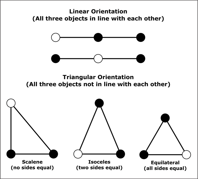
Figure 1: EMS Three-Body Orientations
Electromagnetic Spectrum Three-Body Problem
The simplest example of a communications jamming problem consists of three elements: a jammer (Jx), and two transceivers (TRx). In a geospatial context, their relative orientation to each other is either linear or triangular. There are two linear formations: The first linear formation consists of the jammer at one end of the line, a transceiver occupying the other end, and the remaining transceiver placed in between them (and in-line). The second linear formation is similar; except that the jammer is in between the transceivers (and in-line). Triangular formations occur when the elements are not in line with each other. There are three triangular formations: 1) scalene (unequal lengths amongst the sides), 2) isosceles (two sides with equal lengths), and 3) equilateral (all sides with equal lengths). Figure 1 illustrates the various formations:
To effectively study the links between the three elements (one Jx, two TRx), the following parameters are needed for each element: frequency (MHz), transmitter power (dBm), receiver sensitivity (dBm), antenna gain (dB), antenna height (m), and distances (km) between the three elements. For reactive and cognitive jamming techniques, receiver sensitivity of the jammer is increasingly important; the basis of which is the jamming platform intercepting victim signals, analyzing the signal, then responding with a jamming signal. Note: A reactive jammer is a type of jammer that can sense a portion of the spectrum and immediately transmit a jamming signal when it senses a signal it wants to jam. A cognitive jammer uses machine learning techniques to improve its reactive jamming capabilities.
Communications Jamming States
There are three states of communication link jamming: 1) Neither transceiver can receive a signal from the other; 2) one transceiver can receive a signal from the other, but not vice versa and; 3) both transceivers can receive a signal from the other. These states mirror the standard information “flow” seen in communications models: simplex (information travels in one direction); duplex (information travels in both directions simultaneously); and half-duplex (information travels in both directions alternatively). The ideal jamming state is no information flow in either direction between the transceivers. The next best jamming state is information allowed to flow in one direction only (simplex). The least desirable, and most ineffective, jamming state is information allowed flow in both directions between the transceivers (duplex or half-duplex).
Jam to Signal Ratio (J/S)
To assess the disruption of communications, a common measure of effectiveness is the “Jam to Signal Ratio”, or “J/S.” The J/S ratio is usually expressed in dB notation, of the power of a jamming signal to that of the desired signal at a given point such as the antenna terminals of a receiver. Because both quantities are in decibel notation (decibel milliwatts, or dBm, in this case), instead of dividing “J” by “S” (J/S), one can solve the J/S ratio equation by simply subtracting the transmit signal strength from the jamming signal strength (J – S). For example, if the jamming signal strength at the victim receiver antenna is -100 dBm, and the transmitter signal strength at the same receiver is -110 dBm; the J/S can be expressed as:
J – S = Decibel Value – or – -100 – (-110) = 10dB
If the decibel value is greater than zero, the jamming signal is stronger than the transmit signal at the victim receiver’s antenna. Zero means the signal strengths are equal to each other, and a value less than zero means the transmit signal is stronger than the jamming signal. Negative J/S values usually mean the jamming is not effective.
Communications Link Characterization
Characterization of the links between the elements (Jx and both TRx) can be done mathematically. Depending on the degree of detail desired, the number of equations can range from one to more than a dozen formulas. In this article, we will use:
The two-ray path loss formula Display footnote number:[1]Display footnote number:[2];
- A “flat earth” smooth profile for the earth’s surface;
- An omnidirectional monopole (whip) antenna;
- A frequency band from 30 MHz to 1,000 MHz;
The noise floor of a clean environment;
- A reactive jammer;
- A noise jamming signal;
- A jamming bandwidth that matches the bandwidth for the transceivers;
The two-ray path loss formula is an estimate, because it does not factor in terrain or land cover. Usually, a modified Fresnel Zone Distance formula determines the change-over range (from the transmitter) for using the free space path loss formula (closer ranges) and the two-ray path loss formula (farther ranges). For the frequency band given (30 to 1,000 MHz), unless the antenna heights go above five meters, the Fresnel threshold distance (change-over range) barely exceeds one kilometer. Therefore, only the two-ray path loss formula will be utilized in this article.
Two-Ray Path Loss Formula:
L = 120 + 40log10d – 20log10ht – 20log10hr
Where:
L = path loss in decibels (dB)
120 = constant used for distance in kilometers and height in meters
d = distance in kilometers (km)
ht = transmitter antenna height in meters (m)
hr = receiver antenna height in meters (m)
Situation Example
The key metric in communications link analysis is the maximum effective range between transceivers during active jamming. From the jammer’s point of origin, the jamming signal becomes weaker as it propagates further from the origin. For example, consider the parametric values shown in Table 1, below:
Table 1: Example Parametric Values
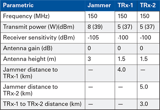
Using the two-ray propagation formula, the path loss from the jammer to the first transceiver is 131.02 dB. The effective radiated power (effective radiated power, or ERP, is equal to the transmit power plus the gain) of the jammer is 39.03 dBm. By subtracting the path loss (131.02) from the ERP (39.03), the estimated jammer signal strength at the TRx-1 location is -91.99 dBm. Using the same process for the link between the transceivers, the estimated communication signal strength from TRx-2 (to the TRx-1 location) is -95.05 dBm. At the TRx-1 location, the jamming signal (-91.99 dBm) is stronger than the communication signal (-95.05 dBm); meaning the jamming-to-signal (J/S) ratio is a positive value of 3.06 dB; which is considered “effective,” depending on the situation.
The unanswered question is how close one of the transceivers has to move towards the other to reach parity with the jammer signal strength (0 dB J/S). Once the “parity distance” is known, then any shorter distance between the transceivers will produce a negative J/S and; the jamming is considered “ineffective.” Given the jammer signal strength at a location, the parametric values for the transceivers, and the basic two-ray path loss formula; the parity distance can be estimated.
To determine the signal strength, subtract the path loss from the ERP, as shown below:
S = Pt – (120 + 40log10d – 20log10ht – 20log10hr
S = signal strength in dBm
Pt = ERP of the transmitter in dBm
120 = constant used for distance in kilometers and height in meters
d = distance in kilometers (km)
ht = transmitter antenna height in meters (m)
hr = receiver antenna height in meters (m)
To determine the “parity distance” between transceivers, the formula for signal strength must be algebraically manipulated to solve for the distance. Using the example data from Table 1, the formula below shows the process to solve for parity distance:
Sj = Pt2 – (120 + 40log10d – 20log10ht2 – 20log10ht1)
Where:
Sj = jammer signal strength in dBm;
Pt2 = ERP of transceiver-2 in dBm;
120 = constant used for distance in kilometers and height in meters;
d = distance in kilometers (km);
ht2 = transceiver-2 antenna height in meters (m);
ht1 = transceiver-1 antenna height in meters (m);
First interim step:
Sj = Pt2 – 120 – 40log10d + 20log10ht2 + 20log10ht1
Second interim step:
Sj – Pt2 + 120 – 20log10ht2 – 20log10ht1 = -40log10d
Third interim step:
(Sj – Pt2 + 120 – 20log10ht2 – 20log10ht1) / (-40) = log10d
Fourth interim step: (parity distance is the antilog):
Dkm = 10log10d
Using the parametric values derived from Table 1:
(-91.99 – 36.99 + 120 – 3.52 – 3.52) / (-40) = 0.40
100.40 = 2.511 km
Where:
-91.99 = jammer signal strength, in dBm, at TRXx1;
36.99 = effective radiated power (power + gain) in dBm, from TRx-2;
120 = constant use for height in meters and distance in kilometers;
3.52 = derived values of the antenna heights for TRx-1 and TRx-2;
-40 = coefficient associated with the distance factor;
0.40 = logarithmic value of the distance in kilometers;
2.511 = the parity distance (antilog) in kilometers, the transceivers can be apart.
Results
With the modified two-ray path loss formula (parity distance process), we have three key pieces of information regarding the TRx-1 site: 1) jammer signal strength at the site, 2) jam-to-signal ratio (J/S), and 3) the maximum distance from another transceiver to reach parity with the jammer signal. The parity distance is the radius of a circle with the TRx-1 site at its center. To maintain communications, the TRx-2 transceiver must be within 2.511 kilometers of TRX-1, and at least 4.0 kilometers away from the jammer site. Should the TRx-2 transceiver move closer than 4.0 kilometers to the jammer, the jamming effect would be greater than at the TRx-1 site. Figure 2 shows the geospatial relationship between the elements and affected areas.
Figure 2: Parity Distance Illustration
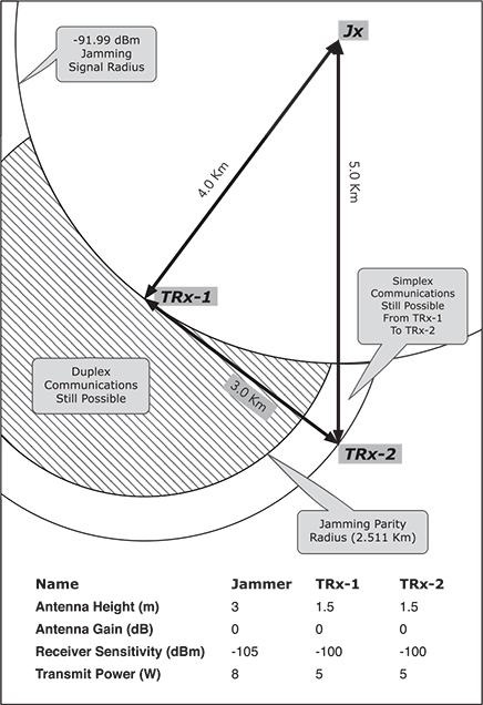
Figure 3: Parity Distance Illustration – Jammer moves closer to TRx-1
Viewable Image – Figure 3: Parity Distance Illustration – Jammer moves closer to TRx-1
Image Caption
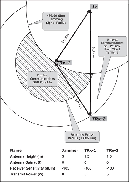
Fig. 3 shows the difference in moving the jammer 1,000 meters closer (moving from 4.0 km to 3.0 km distance) to TRx-1, while maintaining a 3.0 km distance to TRx-2. The parity distance shrinks to 1.886 km, as well as the duplex communications area.
Figure 4: Parity Distance Illustration – Jammer moves farther from TRx-1
Viewable Image – Figure 4: Parity Distance Illustration – Jammer moves farther from TRx-1
Image Caption
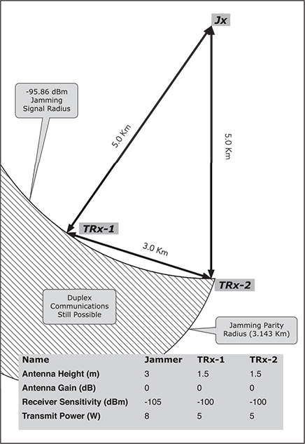
Fig. 4 highlights the difference in moving the jammer 1,000 meters farther away (moving from 4.0 km to 5.0 km distance) from TRx-1, while maintaining a 3.0 km distance to TRx-2. The parity distance expands to 3.143 km, which is greater than the actual distance between transceivers. The duplex communications area correspondingly increased slightly farther than needed, as well.
Conclusion
As shown by the previous examples, electromagnetic warfare officers (EWOs) need to carefully examine not only jamming signal strength at a given point, but also the area around the point where duplex communication is still possible. Assuming the enemy’s disposition is known, EWOs have no control over the enemy’s communications link distances. However, EWO’s do have control over setting their jammer’s disposition relative to the enemy’s communications links. By using maneuver, power and gain, EWOs can affect the enemy’s parity distance for each link and better control areas where duplex communication could persist during a jamming operation.
References: