ESCORT AND MODIFIED ESCORT JAMMING
– By Dave Adamy –
For several decades, we have been achieving excellent results with stand-off jamming, in which (blue force) low-density/high-demand (LD/HD) support jamming aircraft (usually operating in formations of two or more) use high-power electronic attack systems to protect multiple formations of (blue force) attacking aircraft from beyond the lethal range of (red force) radar-controlled weapons.
However, next-generation threats feature significantly greater lethal ranges than legacy threat systems, which challenges the ability of support jammers to operate effectively while remaining outside the lethal range of the radar-controlled weapons systems. Because support jamming aircraft typically broadcast their jamming signals into the side lobes of multiple threat radars, these longer jamming distances reduce the support jammers’ effectiveness by a significant factor. This means that the jammers must operate closer to the radars (and hence in danger of being destroyed) in order to provide effective jamming.
ESCORT JAMMING
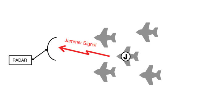
(Although support jamming aircraft often work in numbers of two or more, we are going to use a single support jamming aircraft in our figures this month on order to simplify.) If the jamming aircraft is placed with the protected formation as shown in Figure 1, the protection is effective because the threat radar has its main beam pointed directly at the formation. However, the support jamming aircraft (which typically carries external jamming pods) has a very large radar cross section, which makes it an easier target for the weapon system. Once the escort jammer is destroyed, there is no support jamming protection for the formation, and the remaining aircraft must rely on their self-protection jammers to defeat the threats.
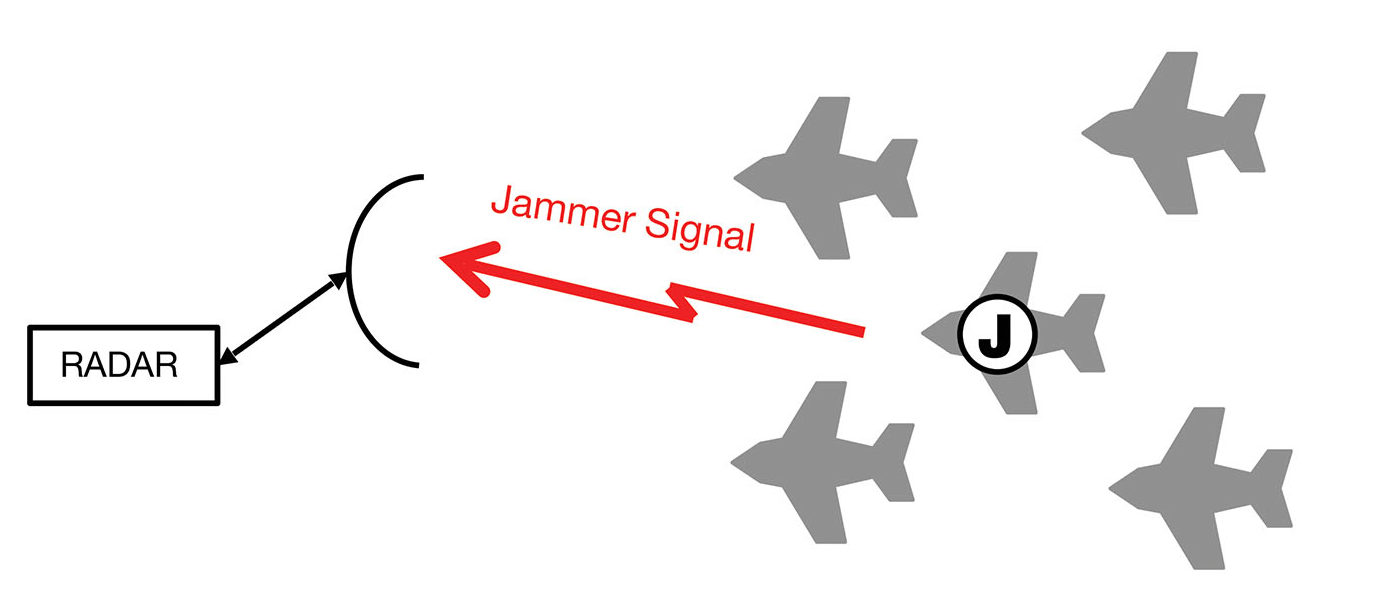
Figure 1: Escort jamming places a support jamming aircraft within a formation of attack aircraft to provide jamming protection.
MODIFIED ESCORT JAMMING
If the jamming aircraft is placed close to the boresight of a threat radar, as shown in Figure 2, its received jamming power in the radar is many dB stronger than it would be if the radar were receiving the jamming power in a side-lobe, as in standoff jamming. For protection, the jammer is kept beyond the lethal range of the radar’s associated weapons. This technique is called “modified escort jamming.”
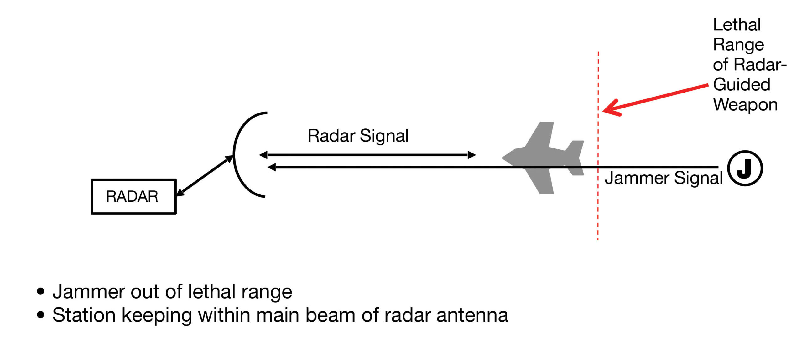
Figure 2: Modified escort jamming places the support jamming aircraft within the main beam of the threat radar but beyond the lethal range of the associated weapons.
Consider some typical numbers. If a new-generation radar provides a missile lethal range of 200 km, as compared to a 30 km lethal range in a legacy weapon system, the jamming-to-signal ratio achieved will be reduced by 16 dB. This will not provide adequate protection for the formation of aircraft. And if the jamming signal is received in the threat radar’s side lobe, the protection will be further reduced by the side-lobe isolation on the order of 20 dB.
If the jammer were right on the threat radar’s bore-sight, the J/S would be increased by the 20 dB, but that would only be for a single threat radar. If the jamming antenna beam width is narrowed (as is anticipated in the next-generation of AESA-based jammers), the jamming effectiveness will be further improved.
MODIFIED ESCORT STATION KEEPING
If the jammer is away from the threat radar bore-sight as shown in Figure 3, there will be a reduction of the received jamming power. This angular offset is the cross-range error as shown in the figure.
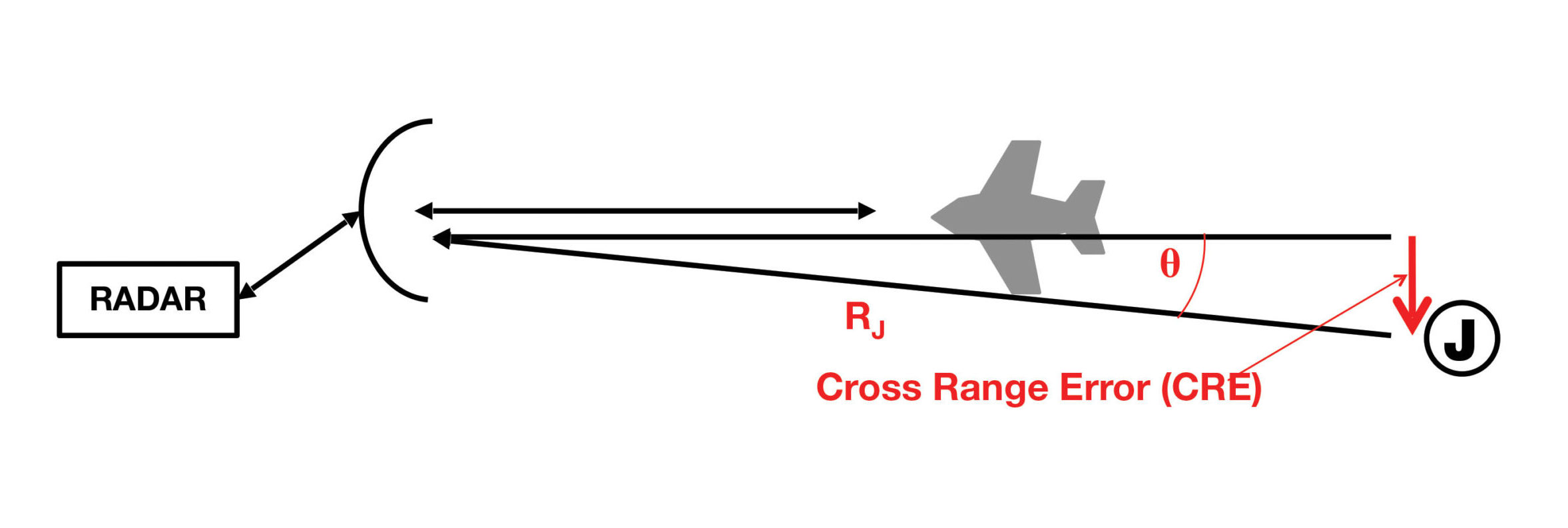
Figure 3: In modified escort jamming, the jamming-to-signal ratio is a function of the accuracy with which the jamming aircraft can be located near the bore-sight of the threat radar.
The error angle is:
ϴ = asin (CRE / RJ)
Where:
ϴ is the offset angle from the bore-sight in degrees,
CRE is the cross-range placement error of the jammer in km, and
RJ is the range from the threat radar to the jammerin km.
Now consider Figure 4. Within the main beam of an antenna, the gain vs. offset from boresight is very well described by the sin(x)/x function. Note that outside the main beam, the gain vs. angle is much less well behaved.
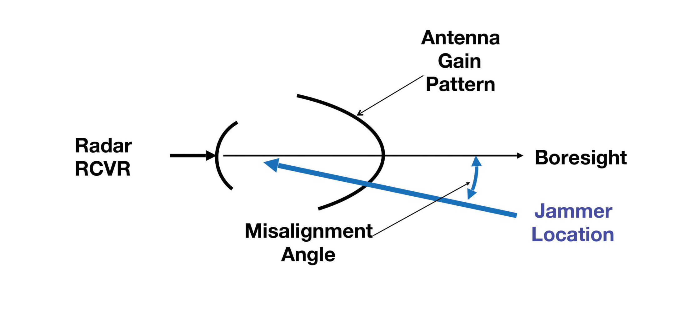
Figure 4: Ideally, the support jamming aircraft would be at the bore-sight of the threat radar. The reduction of the effective jamming power is a strong function of the jammer placement cross-range error.
The equation for the reduction in gain vs. angle from boresight is:
ΔG = 12 (ϴ / α)2
Where:
ΔG is the reduction from bore-sight gain in dB,
ϴ is the station keeping error angle in degrees, and
α is the 3 dB beam-width of the radar antenna
in degrees.
Remember that this equation only works within the main beam. When signals are in the side-lobes, the gain vs. angle data needs to be captured from anechoic chamber testing.
Figure 5 shows a larger scale view of the engagement. There are normally multiple threat radars that might be impacted by a stand-off jammer, but the modified escort jammer only counters a single next-generation radar that has very long range. In this case, the modified escort jammer would focus on this specific threat. The other threats would need to be covered by other jammers (which might also be modified escort jammers).
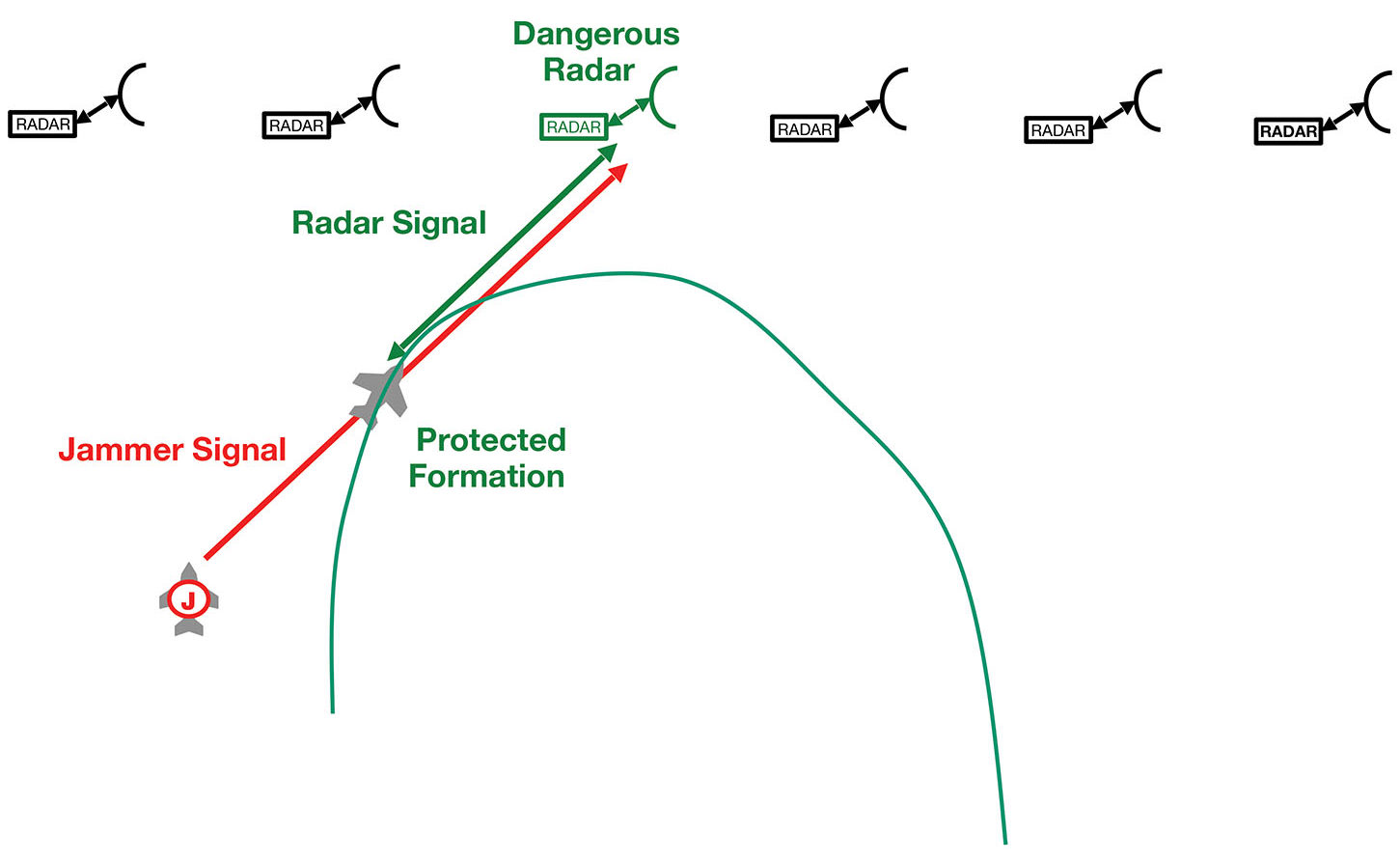
Figure 5: The modified escort jammer optimizes protection of a formation of attacking aircraft against a particularly dangerous threat radar.
The J/S formula for a modified escort jammer is:
J/S = ERPJ – ERPS + 71 – ΔG – 20 Log RJ + 40 Log RT-10 Log RCS
Where:ERPJ is the effective radiated power of the jammer in dBm,
ERPS is the effective radiated power of the threat radar in dBm,
ΔG is the reduction in gain from the offset of the jammer from the radar bore-sight,
RJ is the range from the threat radar to the jammer in km,
RT is the range from the threat radar to the protected formation in km, and
RCS is the radar cross section of an aircraft in the targeted formation in m2.
EDITOR’S NOTE:
This article is part of a longer EW 101 series about “New Electronic Attack Techniques.” If you would like to read the entire series, please consider joining the AOC, and you can access the entire JED archive. ♦
If you enjoyed this article, please share. If you would like to read more articles like this one, we encourage you to join the AOC to receive a copy of JED every month.

